The first thing to do was to mount the solar panel onto the house. The 2007 UK summer may have been something for Noah to write home about but Saturday 15th September was gloriously hot and with the temperature likely to start plummeting pretty fast with the onset of autumn I got the ladders out fast and knuckled down to it!
At the start of the project I had thought about mounting the panel on the roof however I quickly decided against this. For a start, the rear of the house faces south and gets good sunlight from dawn 'till dusk so an easier mounting on the vertical wall of the house was more practical. A vertical mounting also has the advantage that it won't get covered by snow which would block sunlight to a roof mounted panel. The final decider was that there was a suitable area of wall above the flat roof of my extension meaning I wouldn't have to mess about at the top of the ladder to get it fitted into place.
And here it is, all installed....

...or to take a closer look...

On reflection I should probably have spent some money replacing those upper facias!
The panel has an aluminium frame which I had to carefully drill to fit the mounting brackets. I was convinced the drill would slip and shatter it but taking it slowly and carefully did the trick. The wires from the panel go through a hole in the wall which was drilled straight through to the room at the rear. The cables then run up some existing trunking into the loft.

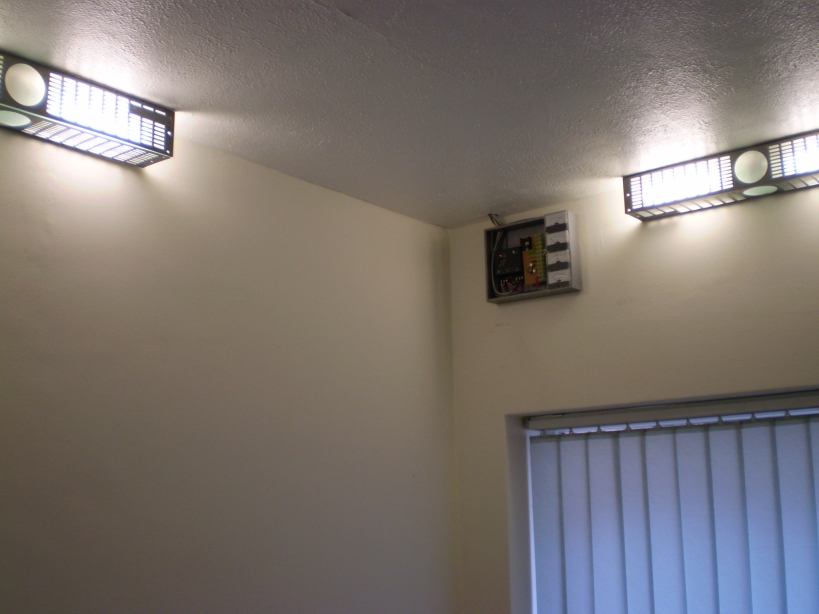
Inside the house I built a 'control panel' from a wooden box that was lying around and this houses the solar regulator/charge controller as well as the current and Volt meters. This picture shows its location on my landing above the stairs. It's only just been screwed to the wall here and isn't yet complete. Check out my cool lights - I made 'em about seven years ago out of spare 19" rack parts!

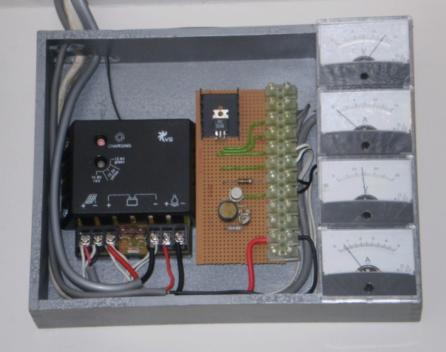
A closer look at the (incomplete) control panel is below. I intend on eventually fitting a cover to hide the gubbins and the cabling that runs upwards through the ceiling. I'll leave a window in it though so that the LED status indicators can still be seen.
The black box is the solar regulator/charge controller. On the right are the meters which show (from top to bottom) battery voltage (15V FSD), load current (15A FSD - although the solar regulator is only rated at 5A), solar panel voltage (30V FSD as the panel generates up to 22V with no load) and solar panel current (5A FSD - the most I've seen out of the panel is 700mA in strong sunlight). Each meter has two 3mm LEDs connected in series to illuminate the dials in darkness. I wanted green LEDs but only had red in my junk box (and I have to admit that red doesn't work very well when it comes to panel illumination!). The battery meter rarely moves but it's handy to have so you can see how it is bearing up under load. I chose these meters with their respective Full Scale Deflections (FSDs) but I could have gotten away with lower values for all but the battery voltmeter. It doesn't hurt to have higher numbers in case of future expansion though.
The stripboard down the middle of the box has plenty of room available on it for mounting components should I decide I want anything extra running in the control box. At the moment there are a handful of components mounted on it and their job is to control the aforementioned LEDs used for meter illumination. A Light Dependant Resistor (LDR) is being used to turn on the meter illumination when the room is dark while saving a bit of battery power by turning off the illumination in normal daylight or when my ace landing lights are on. Although not at all essential for this project, the schematic of this circuit is included below for anyone interested.

The component values quoted are just what worked for me. I recommend you breadboard the circuit first if building one and have a play with various resistor values to see what works best in your lighting conditions and with your LEDs. Use the potentiometer to make adjustments but make sure you have at least 1k of resistance where I have a 5.6k resistor to prevent the transistor becoming overloaded in the event of the pot being turned down to zero. The two series LEDs are repeated for each of my four meters. This circuit isn't brilliant but it was quick to construct and I had the parts to hand in my junk box (any general purpose NPN transistor can be used - doesn't have to be a BFY51). This method doesn't have a nice clean on/off threshold and in fact the brightness of the LEDs changes according to the brightness of the room. I might come up with something different in the future as I'm not completely happy with its operation. Notice too the 7805 voltage regulator. I could have run the circuit straight from the 12V leisure battery (with adjustments in resistor values of course), but as the battery voltage may fluctuate through charging and heavy load, I used the regulator to smooth out the fluctuations and provide a constant 5V. I used a hefty 1A regulator with heat sink (although the LDR circuit only takes a few miliamps), because the regulator output is wired out elsewhere in the house to drive some other circuits that require 5V rather than 12V.
In the picture below, installation is underway. The battery is on an MDF board in the loft and there is a jumble of wires going to a junction box which houses the 12V solar regulator output and the 5V 7805 regulator output. Various cables disappear off from this junction box to the sockets and circuits around the house. Notice the two switches - one isolates the panel from the solar regulator while the other cuts off the battery. These are in place so that the whole thing can be shut off for maintenance work or when I jet off on holiday. If I were doing this project again I'd incorporate the switches into the control box, but here they're an afterthought. Maybe I'll move them one day so I don't have to go into the loft to push 'em when I need to.

I had to distribute wiring throughout the house in order to connect various items to the battery. I decided upon fitting standard 12V automotive sockets in the rooms (the cigar lighter sockets used in cars) as these were easy and cheap to obtain and it meant off-the-shelf car accessories could be interfaced easily with my battery. Certain rooms would need these sockets fitted which meant cabling had to be run from them to the loft. I don't like unsightly cabling being on show around the house so running the wires without them being noticable was a challenge. Fortunately this project came about at the right time as one of the downstairs ceilings has been removed after a major water leak from the bathroom had damaged it. Before I put a new ceiling up I ran as much of my cabling as possible in the ceiling void which gave me access to three rooms and the outside porch and there also happened to have a handy riser running all the way to the loft for easy cable drops. To get a cable to the living room on the other side of the house, I ran the cable across the loft, dropped it down through a built-in wardrobe in the bedroom (which kept it out of sight) and down trunking in the corner of the room behind some shelves. In fact, the only visible signs of the whole wiring installation, other than the sockets, is this one piece of trunking.
I wasn't able to get panel mounted automotive sockets so mine are on short flying leads. I fitted standard double-backboxes to the wall and used blank faceplates that had two holes drilled out to allow the socket wiring to emerge. Rubber grommets around the holes prevent the wires being cut by any sharp edges and cable grips on the rear of the faceplate provide strain relief on the wiring should the socket be pulled. The picture below shows the living room outlet. The left hand socket has nothing connected to it in the picture while the right hand socket has a converted uplighter plugged into it (the base of the uplight can be seen in the picture). This outlet is different to the others because it has a third connector mounted on the top of the backbox and the output of this connector is 5V DC as it is connected to the Voltage regulator output from the control panel. This is not an automotive socket, rather a wierd large jack socket I had in my junk box. The different socket presentation was deliberate as I didn't want any 5V devices to be plugged into 12V sockets. The jack plug that goes with it is connected to some LED colour changing 'mood lights' I got from the Gadget Shop a couple of years ago and those are the only items that plug in to the 5V outlet at the time of writing.

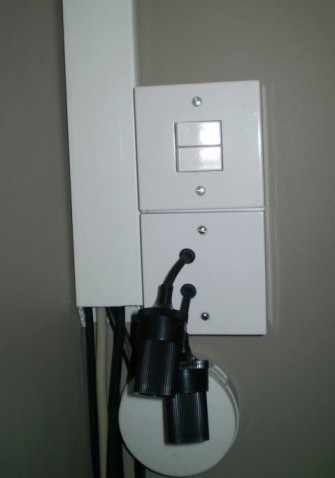
The sockets fitted in another room (pictured below) show another variation in that they have been mounted sideways (because of space constraints) and are switched. The switches were included only in this room because I planned on connecting some unswitched shelf lights and my inverter to them. Ignore the trunking and other cabling going on in this picture - all part of a different project!


