A funny thing, unhealthy urges. We all get 'em. Whether it's to scoff a questionable kebab, drink the expired booze from a dusty bottle pulled from the cupboard of Christmas past or to place one's willy inappropriately into some sort of foodstuff, we've all given in to them, yes?
Which reminds me, I must add a couple o' jar's of Marmite to the shopping list...
Anyhow, sometimes I get the unhealthy urge to make something pointless. Not something useful such as my aquarium temperature meter or something aesthetic such as my digital picture frame, but something that serves no purpose other than simply 'being'. Usually such projects are based around some form of lighting and the urge to build them stems from one of three reasons:
- Something tantalisingly semi-transparent is just begging to have a light fitted behind or into it for extra effect.
- I get the idea that I can design and build a circuit to produce a particular lighting sequence and go ahead just to prove the theory regardless of whether there is any real practical application.
- I have certain component or case parts that have been hanging around far too long and deserve to be thrown together to become something interesting.
And so it is that this project happened to tick all three of the above boxes.
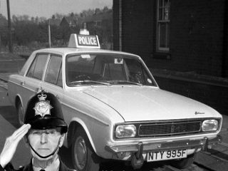
The roots of this project go back to my unhealthy obsession with rotating mirror lights - the 'flashing' lights you used to get on top of police cars. Actually they didn't flash at all, the bulb remained illuminated while a concave mirror swept around it focusing a beam of light in one direction while at the same time obscuring the light in the opposite direction rather like a miniature lighthouse. You don't see them so often on emergency vehicles these days as strobing LED clusters are taking over and are nowhere near as much fun. As a kid, It always annoyed me that the American police cars in the movies had cool blue/red light bars crammed with mirrors and bulbs set to rotate in staggered sequence while British bobbies had a single blue tit mounted on top of their low-tech fartbox squad cars. I mean, if you were the Kray twins and you'd just blown some slaaagggg's kneecaps off wi' yer shootah, which of the below would be more likely to shit you up and make you respect the authoritah, the US or the UK version??
 |
 |
|
| "Drop your weapon, you have thirty seconds to comply, mother fucker." | "Now then, how about we sort this out down at the station over a nice cup of tea?" |
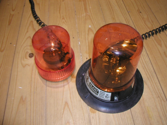
My first rotating mirror light was rescued from a truck scrapyard back around '92. Since then I've sourced others although with these things you get what you pay for. The cheap ones used to cost about a tenner from automotive shops and were equipped with a shitty tungsten bulb, low quality reflector and rickety noisy motor/drive while the decent ones cost at least three times as much but had a bright halogen bulb and ran smoother and quieter.
A cheap version (left) and the proper job.
M' old mukker Nigel, having discovered my penchant for such things, snapped up some little versions that were a quid apiece at some dodgy backstreet market about ten years ago. You don't expect much for a quid, in fact it's quite amazing that for just a quid you can get something that contains a motor, bulb, custom moulded plastic *and* an elastic band gearing mechanism, but nonetheless he managed to obtain four of 'em for me and eventually forgot that I owed him four shiny pound coins which made me a winner all round. Credit where it's due though, and if I were wearing a hat, I'd doff it toward the Chinese children who worked so hard to assemble this product for such a measly price tag.
As I don't have a hat, I'll drink to their health instead. Assuming they survived the last decade. I like to think they did.
Anyway, to cut a boring story short, you don't expect much for a quid and sure enough, inserting three AA batteries showed these things up for the novelty that they are. The bulb glowed dimly, the motor spun the ineffective reflector too speedily and jerkily, and the batteries, if left to their own devices, would piss out all their energy far too quickly. In short, they were pretty crappy. Which is fine 'cos they were only a quid apiece and I never paid Nigel for 'em.
So, they went on the shelf and spent ten years taunting me with their sexy semi-translucent housings and their potential to become more than some shoddy low cost mechanical novelties assembled by poverty stricken children.
More recently, I began wondering if I could create a rotating mirror light effect by removing the scrappy mechanics and fitting LED's driven in sequence to produce much the same effect. If successful, I'd have an interesting lighting installation to fit to the ceiling of my evil lab of super doom! What's not to like?!
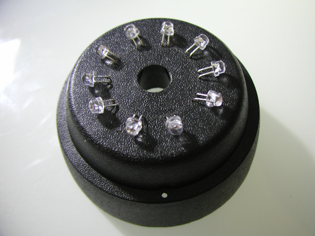
If I fit ten orange LED's into each unit as above, then instead of individual motors running at slightly different speeds, I could build a single sequencer to control all four units to give them an ordered rotation effect!
Obviously with motivation like that, I had to act fast, and I knew just the chipset to help me - the 4017 decade counter.
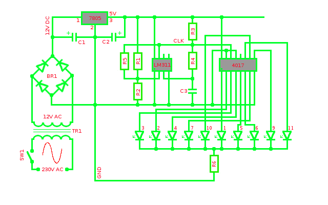
The 4017 decade counter is a chip I came across when at Coventry Technical College in 1992. It has ten outputs (duh!) each switching on in turn for every pulse received on its clock input. It can therefore drive ten LED's in sequence, one after the other, in a configuration such as that shown below.
Parts list
| Resistors | Capacitors | Semiconductors |
| 150k, R1, R2, R4, R5 | 1000uF, C1 | 7805 Voltage regulator |
| 2K7, R3 | 100uF, C2 | LM311 Comparator |
| 200R*, R6 | 0.47uF, C3 | 4017 Decade counter |
| Bridge Rectifier, BR1 | ||
| Miscellaneous | ||
| Transformer, TR1 |
*Depends on LED characteristics and source voltage in use
The output pin sequence of the 4017 is: 3, 2, 4, 7, 10, 1, 5, 6, 9, 11 so LEDs hooked up to these pins in this order in a common cathode configuration such as that shown above will produce a 'moving dot' display with each LED illuminating in turn from left to right. Similarly a 'moving hole' display can be achieved by using a common anode configuration and sinking the current into the 4017 rather than sourcing it from the 4017.
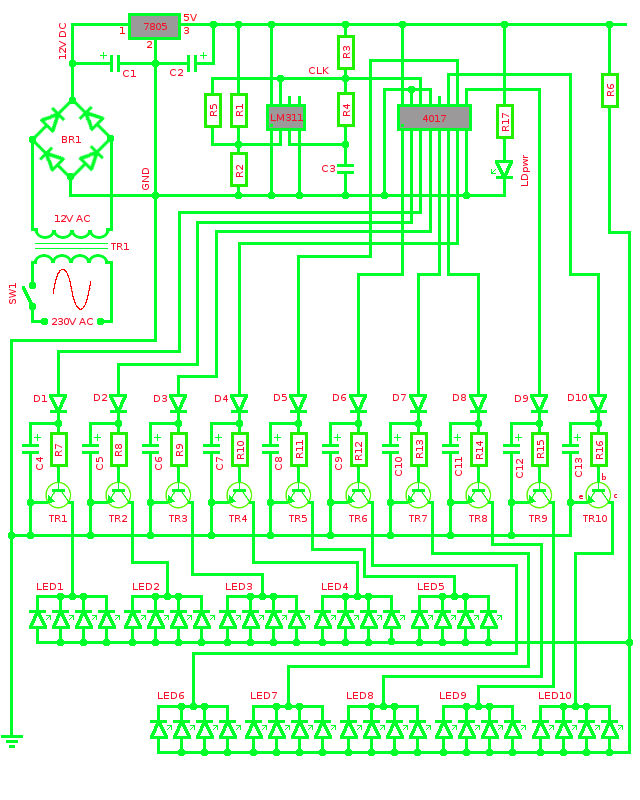
The only trouble is that this is a very 'digital' effect - each LED lights up in turn but as one comes on, the previous LED turns off thus giving the appearance of only one being illuminated at any one time. For an application such as this where I am attempting to recreate the analogue sweeping motion of a rotating mirror, this kind of output just wouldn't look right. I therefore needed to modify the output stage to give it a softer look. And besides, I wanted to drive four LEDs at the same time - one in each housing, and the 4017 might not be able to handle that. Clearly some kind of output manhandling was gonna be required. So I came up with this...
Parts list
| Resistors | Capacitors | Semiconductors |
| 150k, R1, R2, R4, R5 | 1000uF, C1 |
7805 Voltage regulator |
| 2K7, R3 | 100uF, C2 | LM311 Comparator |
| 100R, R6* | 0.47uF, C3 | 4017 Decade counter |
| 7k5, R7 - R16 | 10uF, C4 - C13 | Bridge Rectifier, BR1 |
| 470R* **, R17 | BC107, transistor TR1 - TR10 | |
| Miscellaneous | 1N4148, diode D1 - D10 | |
| Transformer, TR1 | LED, 5mm high brightness orange | |
| LEDpwr**, 3mm red |
*Depends on LED characteristics and source voltage in use
** Used as a power indicator, not an essential part of the circuit design
Let's go over this in detail. First of all, we have the power supply. Normally I don't like to make my own power supplies. Mainly because I have a pile of power bricks from all sorts of redundant applications such as 33.6k external modems and tape based telephone answering machines and as they are generally designed by people much cleverer than me and come in pre-moulded cases which keep me safe from drunkenly dicking around with the rather unhealthy mains side of the transformer, I'm happy to accept their low voltage outputs and put them back to good use. In this case however, space was going to be at a premium as I wanted to fit both the control circuitry and power supply into a standard UK double-gang patress box. Fortunately, amongst my crap, I found a power supply I'd made years ago complete with 250mA transformer, bridge rectifier and smoothing capacitor all small enough to get a new lease of life in this application! Excited?! Why, I nearly spunked my corduroys!
And so we have TR1 ramping down 230v AC to around 12v AC and BR1 turning the AC into DC. C1 smooths the DC waveform and finally the 7805 regulator along with C2 provide a nice clean 5v to drive the circuit.
When it comes to the timing of the circuit, instead of using a 555 timer as I have in previous projects, I decided to try something different. Don't get me wrong, the 555 is ace, but as I keep telling my wife during foreplay, there are other ways to generate a square wave, so instead I'm using an LM311 comparator that happened to be hanging around. At power-up capacitor C3 hanging off the comparator's inverting input is discharged so is at a lower potential than the non-inverting input being fed by the R1/R2 voltage divider. The output of the comparator on pin 7 is therefore high. Connected to that output is feedback resistor R4 which raises the voltage on the inverting input and starts C3 charging. Once the voltage on the inverting input exceeds that of the non-inverting input, the comparator output switches low. C3 then starts discharging and, once it drops below the non-inverting input, the output switches high again. And so the cycle continues - at a rate of about 10Hz with a 50% duty cycle using these components. R5, a second feedback resistor, aids with switching states while R3 acts as a pull-up to counter the high impedance of the output.
And so coming out of pin 7 of the LM311 is a lovely neat square wave which feeds into the clock input of the 4017 decade counter. Every time a clock pulse is received, the 4017 switches high the next output in turn. After the tenth output, the 4017 goes back to output 1. Incidentally, although I'm not using them here, there are a couple of other interesting pins on the 4017. Pin 15 is a reset (being held low in this application), however if you wanted fewer outputs then you could connect one of the output pins to this reset pin to produce a sequencer with 1-9 outputs (although just 1 would be rather pointless). Pin 12 is a 'carry out' pin which is high for the first five clock cycles and drops low for the next five cycles allowing later stage circuitry to be sequenced after all ten 4017 outputs have clocked through. Interesting huh? Yes, I thought so too.
So we know that the 4017 ain't gonna quite do the business outta the box but as you can see from the schematic, the output stage has now been modified with diodes, transistors, resistors *and* capacitors! Let's look closer!
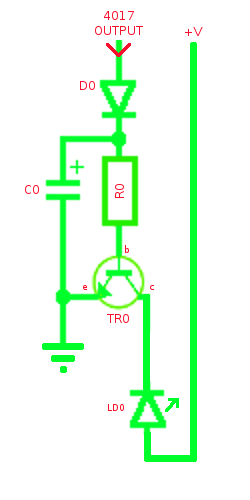
Here the LED is in a common anode configuration with a constant voltage being applied to it however assuming the 4017 output is low (off), the LED won't illuminate because its cathode is connected to the collector of transistor TR0. With the 4017 output low, there is no current through D0 and R0 into the base of TR0 so the transistor is in cut-off and the path between collector and emitter is open keeping the LED cathode disconnected from ground. Suddenly the 4017 output goes high for about 100ms. Current now flows through D0 and R0 and across the base-emitter junction of TR0 which immediately goes into saturation and closes the collector-emitter path. Current can now flow through LD0 and across the collector-emitter junction to ground causing the LED to fully illuminate. The high 4017 output also starts capacitor C0 charging.
After 100ms, the 4017 output drops low again however the charge stored in capacitor C0 causes it to act like a battery and it starts discharging. It can't discharge back into the 4017 as diode D0 blocks the path so it has to discharge across the base-emitter junction of TR0. As C0 discharges, the voltage drops and as the voltage drops it causes the collector-emitter junction to slowly start opening. This gradual opening of the collector-emitter junction makes the LED fade off as the resistance across the junction increases, so we get that nice analogue fade effect we want instead of the light cutting off suddenly and cleanly. If left for long enough, C0 would discharge enough for the transistor to reach cut-off and fully extinguish the LED, but with these component values there is still some light output by the time the 4017 output goes high again, switching the LED back to full brightness and recharging C0 for the cycle to begin again.
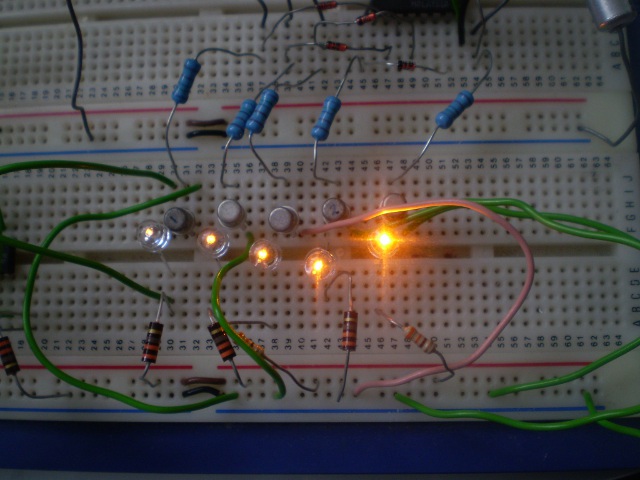
A snapshot of that fade effect when the circuit was in the prototyping stage. Of these five LEDs, the rightmost is the only one being fully powered by a closed C-E junction while the light output of the previous four is in increasing stages of decay as we look from right to left. These LED's are only providing any illumination at all because of the discharging capacitors trying to keep open the C-E junction of their corresponding transistors which haven't yet reached a cut-off state.
As well as providing this fade effect, these components allow me to hook up four LED's on each of the 4017 outputs as the transistor is now driving the load rather than the 4017 chip itself. I'm using BC107 transistors which, if I remember rightly, should allow me to hang up to 100mA off 'em which is probably about twice what I need. R0 is there to prevent the high 4017 output from frying the base of the transistor.
With the circuit designed, I moved on to the contruction phase which was quite tedious and not nearly so much fun. This was mainly due to the amount of wiring connections involved. With ten LED's per housing, two pins per LED and four housings, that's.. uh.. 80 connections to have to solder within the housings and 44 connections back at the driver board (ten cathodes plus one common anode per housing). Added to the pain was the fact that in my hungover state I wired the whole bally lot in a common cathode configuration and, when the hangover cleared, I remembered the circuit required a common anode configuration so I had to spend two hours de-soldering and rewiring the frigger! Gaa!
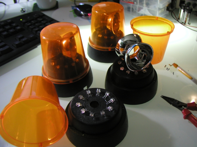
Anyway, I started by removing the mechanical gubbins. The motor, laggy-band driveshaft and bulb were all taken out and ten LED's fitted onto each circular base.
I left the reflectors in place although their days of spinning around were now numbered. They still help to add to the effect of the thing. To hook the four housings together, I'm using a length of 22mm plastic pipe from Homebase. Eleven wires feed from a central hole cut into the pipe to holes where each housing will be fitted. Ten wires will be used for each LED cathode while the eleventh wire provides the source voltage to the common anodes.
In order to squeeze the circuit board into a 2 gang patress box alongside the transformer, I built the main part of the circuit onto one board...
...and built the output stage on a second board which sits atop the first like a daughtercard.
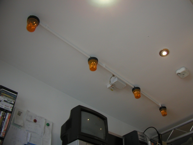
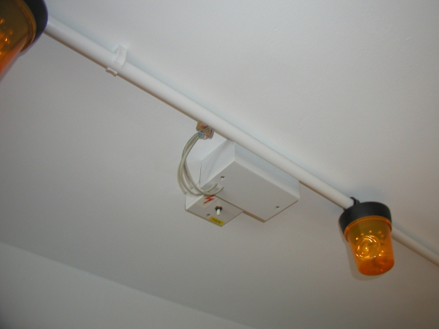
Here's the final construction with the four housings clipped to the pipe and the connections fed to the circuit board that is hidden in the double gang patress box with the transformer. An adjacent single gang patress box houses the power switch and covers the hole in the ceiling where the mains cabling disappears up into the room above. Originally I was going to have all four running in the same synchronisation but instead I wired them so that LED1 in each was offset by two LED's in relation to the housing on the right. This gives the thing a 'rolling' effect from right to left as each is approximately 1/5th of a rotation behind it's neighbour on the right. The LEDs are wired so that the sweeping 'movement' travels anticlockwise.
Below, a close up of the patress boxes. The 44 connections to the LED's are terminated on a piece of stripboard as they exit the pipe and are reduced to eleven connections which feed back into the patress box.
As I'm sure you'll agree, it's a pretty natty, if pointless, addition to my evil lab of super doom and is sure to draw admiring glances from all my many friends when they visit.

